Wednesday, October 16, 2013

Drone Mapping the Pyramids of Zuleta


Drone derived slope model of portion of Zuleta.
The Pyramids of Zuleta are one of the hidden treasures of the Andes.  Built around 1,000 years ago, by the native Caranqui people, these earthen mounds and platform pyramids dominate the landscape near Hacienda Zuleta.  Unlike much of our planet, high resolution aerial imagery and digital elevation models are unavailable for this part of the world.  This is due to the fog that often blankets the area and the agrarian nature of the region. As a part of a team of archaeologists who visited the site in the August 2013, we aimed to change that.

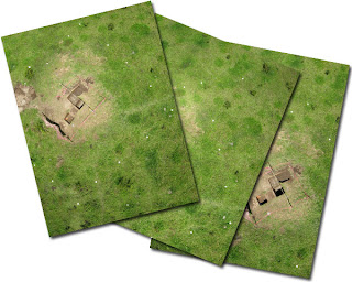
Comparison of Landsat Imagery (best public data available) vs. UAV
Using a small, hand-launched, Unmanned Aerial Vehicle (UAV aka drone) equipped with a downward facing camera and a sophisticated autopilot system, we documented the site as it has never been seen—from extremely low altitude and at high resolution.  This was a challenging task as most of the pyramids are located in the bottom of steep constricted canyon inhabited by Andean Condors.  To make things more challenging there were high winds, clouds, and quirks of the micro-climates within the canyon to contend with. In spite of that, we were able to fly nine missions and collect hundreds of photographs in just a couple of days.
Programming the UAV while in flight.
The UAV flies in a defined pattern and as it collects photographs. The onboard autopilot insures that each image has 60% or more overlap with adjacent images.  These overlapping images allow for the data to processed into 3D and digital terrain models (DTMs) using photogrammetric and cutting edge Structure from Motion technologies.  All of the data are GIS ready. While basic processing allowed us to see the mapped data in the field, it was necessary to further develop it using a high-end processing farm in Maryland, once we were back in the States.

Radiance scaled enhancement of UAV data.
This approach has already led to the discovery of many more mounds that are not obvious to the naked eye but stand out in the data.  Furthermore, it is the first time the detailed spatial relationship between each of the earthen structures can be explored with precision.  This data will be used to track the condition of the mounds over time and has created a digital snapshot of their current state for future generations to ponder. This was accomplished with only a few days of fieldwork and under harsh conditions.  To create a map of similar accuracy using traditional survey approaches would have taken weeks and lacked the aerial imagery this approach provides. 
Pyramids deep within the canyon.
Our team has conducted similar mapping missions in Australia, Belize, Belgium, Fiji, France, Germany, The Republic of Kiribati, Peru, and South Africa. We look forward to continuing these sorts of projects elsewhere and helping to preserve and understand our past.


Hand launching the drone.
The archaeological mapping and processing team included Chet Walker and Mark Willis.  The rest of the archaeological team was made up of Steve Athens and David O. Brown. Athens and Brown are experts on the archaeology of the Andes and have worked for decades in the region.  We would like to thank Fernando Polanco Plaza, the general manager of Hacienda Zuelta, for his hospitality and dedication to preserving the rich heritage of Ecuador.


Tuesday, November 8, 2011

Determining Rock Art Deterioration Through Time:

Automatic Change Detection with SfM


Structure from Motion (SfM) is a very useful tool for creating 3D models from unreferenced images. Since SfM can create highly detailed models from historic film and digital photographs, it is particularly helpful in examining changes in an object over time.  In this short post I'll show how data collected at a pictograph site in 2003 can be compared with more recent data to pinpoint areas of deterioration in a systematic way.

The pictograph we'll be looking at is located at 41CX2 and is part of a prehistoric site on the eastern edge of the Pecos River in West Texas. I like to use data collected from this site because there are no issues with making it publically available. I also go back to it because there are both older digital photographs of the site and much older historic photographs archived at the Texas Archaeological Research Laboratory (TARL). This provides a nice test bed of data to take advantage of.

In order to compare a set of historic photographs with modern ones, aligning the two image sets to each other is critical. This can be difficult because photographs contain all sorts of lens distortions and it is hard to reproduce the exact angle of a historic photograph with a modern camera. It may sound like a simple task to overlay one image on another in Photoshop but getting an exact alignment between two photographs taken at different times, is almost impossible. SfM can aid in the alignment process.  By analyzing the structure of the object in the photographs, SfM can remove virtually all distortion when a 3D model is created. Therefore, if you create one 3D model from historic photographs and another 3D model from more recent images, the two can almost perfectly aligned to each other. The easiest way to accomplish the alignment is by assigning the same coordinate system to each model and then converting those to a Digital Elevation Model (DEM).

2003 and 2011 SfM models aligned.

In this example, I have assigned the same arbitrary coordinate system to each model with the X and Y axis approximately in alignment with the natural surface of the rock. In other words, the Z, or elevation value, is greater the closer it is to the viewer and vice versa. With both models now in the same space and orientation, the Z values of the vertices can be sampled to create a DEM.  It is important to note the word "sample" here because each cell of the DEM is composed of a value derived from the average value of the vertices that fall within that cell. If cell sizes are not the same or have a different origin point, the DEM values can vary slightly for what appears to be the same location. In our example the 2003 3D model covers a slightly larger area than that collected in 2011. Due to this difference in area, the DEM cells are slightly offset. To help reduce this minor alignment problem, the 2003 model could be clipped to the same size as the 2011 data but for this project I left the models in their original state.

2003 DEM

2011 DEM

The result of subtracting the 2011 DEM from the 2003 DEM.
Areas of red have had the greatest change.

Having created the DEMs for the 2003 and 2011 models, each DEM was loaded into ArcGIS. To compare the changes between the DEMs over time, the 2011 data was subtracted from the 2003 data. This was done with the Spatial Analyst's Raster Calculator tool. The resulting DEM highlights those areas of significant change in red and the more stable areas in blue. As mentioned previously, the DEM cell values do not match exactly so there is minor variation visible across the model.  When the difference DEM is transposed against the pictograph images, areas of deterioration are obvious. While it is certainly possible to visually compare the photographs from different time periods and see that damage is taking place, this process allows for a systematic and quantifiable means of assessing that change.

2003 image imposed over differences map. 
2011 image imposed over differences map.  
Closeup of 2003 imagery and differences map.
Animation showing change from 2003 to 2011.

The implications for using this technique are exciting. Since SfM can work with historic film photographs, many older photographs of rock art panels can be analyzed and historic 3D models created. Furthermore, the process need not focus on pictographs; historic aerials can be converted to DEMs and geomorphological changes examined or the process could be applied to underwater photography to examine the morphological changes of coral reefs, etc. There are many possibilities.

Wednesday, November 2, 2011

3D Prehistoric Pictograph Printing

A tutorial on hard copy printing of virtual models using 3DS Max and Shapeways


3D hard copy printout of pictograph.

There are now several rapid prototyping/3D printing services available for creating hard copy models of virtual creations. Here, I walk through the steps for preparing a Structure from Motion (SfM) model for color/textured printing using the services provided by Shapeways.com and 3D Studio Max 2009.  Shapeways is an economical online service that accepts the upload of 3D files and then sends you a hard copy of that model you can hold in your hands.


Other than it just being plainly awesome, why create virtual models of rock art or other archaeological phenomena? Here are some reasons to consider:

  • Virtual models are easy to share with other researchers via the Internet. This may broaden interaction and scientific inquiry.
  • Public access to 3D models allows for remote or extremely delicate objects to be explored and enjoyed.
  • People love to touch archaeology. Holding a replica can fulfill some of this desire without damage to the real thing.
  • Elements that are not obvious in 2D may stand out in 3D, giving new insight about the object.
  • 3D models create a virtual snapshot of an object in time that can be compared with future models to consider impacts and changes to the real object over time.
  • The 3D model can be modified so that certain aspects of it can be exaggerated. A good example would be the stretching a petroglyph model along its depth axis, making ridges taller and grooves deeper. Thus helping to show faint detail on the original.
  • Using emerging Structure from Motion (SfM) and photogrammetry techniques, highly accurate and detailed models can be created from historic photographs. This can allow for unique 3D views of lost elements or destroyed sites to be examined in new ways.

Creating a "water tight" 3D model in 3DS Max**
**Please note, I am not an expert with 3D Studio Max. If anyone has a better way of doing anything described in this tutorial, please let me know.


Follow along with this tutorial on Youtube..


I start with the 3D model in Alias Wavefront OBJ format. The 3D was made from a series of photographs of a small prehistoric pictograph found in a rockshelter above the Pecos River in West Texas. The file consists of about 102,000 polygons and a texture in JPG format. 500,000 polygons is the largest number of polygons that Shapeways can currently handle. I purposefully created the model to have a little less than a half million polygons because additional structure will be added to the model.

The imported Alias Wavefront OBJ File in 3DS Max.

The first step is to import the OBJ file using Max's import command (File>Import). This particular 3D model is very flat and has no volume.  Its shape is analogous to a slightly crumpled and twisted piece of paper. In order for the model to be printed, it must have volume and depth. It also has to be "watertight", lacking any holes or open faces. To give the model volume in Max, it is extruded by selecting it and then clicking the (Modify>Element) command and then selecting the entire model, and extruding it. In this example, it extruded it by a value of 0.004.

Extruding the edges of the model.

There are a few things to consider when the model is extruded.  The model needs to be thick enough to be strong when printed but the thicker it is, the more it will cost to print.  The hard copy price is calculated by volume and the material the object is printed from. The internal geometry of the model must be considered, too. With only the exterior edges of the model being extruded, enough of a buffer between the "bottom" of the model and extruded edge must be present or the model will be fragile or have holes.
Once the extrusion is just right, the model is converted to a mesh (right-click selected mesh>covert to editable mesh) and then a "Cap Holes" modifier is added (Modify>Cap Holes). This closes the "bottom" of the model and gives it volume. It is important at this stage to examine the model carefully and make sure nothing strange is going on with the geometry. To check this, I look at the model in wireframe mode and also render it (F10) from several vantage points. Certain faces may need to be adjusted (Modify>polygons>faces). The Cap Holes modifier is automatic and sometimes does not work very well. Be sure to check the model statistics to insure the model is still below 500,000 polygons. If it is not, the model needs to be decimated.

Converting the model to a mesh.

Adding the "Cap Holes" modifier.

Once satisfied the model will be strong, but thin enough to print affordably,  the model is selected and exported as an STL file. The STL is then opened in netfabb Studio and tested. Netfabb is a free utility and details of its use are described in this tutorial. I use netfabb not only to identify problems, but actually fix the issues in Max. I do it this way because texture location is lost when the file is exported to STL. Luckily, most of the time, netfabb does not find any issues with the model.

To print the model in color a JPG, or similar texture map, is required. The resolution which Shapeways can print at is very limited in regards to the texture map. The maximum is 2048 x 2048 pixels; so, I resize the texture map in Photoshop and then apply that map in Max to and review it for proper alignment.

Applying the texture to the model.

Next, the 3D model needs to be scaled to the size it will be printed at.  This can be a little tricky and can take some trial and error. I have found that scaling a model to about four meters in Max produces a hard copy printout about 15 cm in size.


Scaling the model up to "4 meters" in size.

Models that are to be printed with textures must be exported to VRML 2.0 (aka VRML97) format. In order to do this go to (File>Export>VRML). Check only "Indentation" in the Generate options section, leave Polygon Type as Triangles, set the Digits of Precision to 6, turn off the Bitmap URL Prefix radio button, and then click Ok. This will create a VRML formatted file with the suffix WRL. Next, compress the newly created VRML file along with texture map into a zip file. Make sure the zip file is less than 65 megabytes in size (it should be considerably smaller than that).

Exporting the textured 3D model to VRML97 format.

Upload the file to your Shapeways account. Set the upload units to millimeters and start the file transfer. An email should arrive from Shapeways saying that the file has arrived and later, another email describing if the model was viable or if there was a problem.

Uploading to Shapeways.

With a successful upload to Shapeways website, the size of the model can be checked and the cost of printing from different materials assessed. Keep in mind that only the "full color sandstone" option works with textured models. If the costs are too high or the model too small, recreate it at a different scale and re-upload. Once the model is the right size and price, place the order and it should arrive within a couple of weeks.

Picking the material to print the model in.

My model measures 10.2 w x 3.7 d x 14.3 h cm in size and cost $128.89, including shipping.  The model appeared on my door step six days after it was uploaded.  3D printing is still in its infancy, especially for color, and the final model is not quite a perfect recreation.  The baking/fusing process used made the colors slightly darker on the model than the original. The model also has contour-like shapes comprising its surface.  This effect is caused by the laser that built up of the surface of the model, one layer at a time. Additionally, some of the rock edges are not as crisp as the real thing.  Problems such as these are likely to go away as 3D printing evolves. All in all, the model gives a fairly accurate reproduction of the original surface of the rock and the pictograph's association with that surface.


3D printout.

Closeup photo of contour-like stair-stepping on the model's surface.

One thing I had not noticed when I visited the pictograph in person, was the slight protrusion of rock between the legs of the anthropomorph. Looking at the virtual model and hard copy, it becomes obvious that this element of the natural rock helped inform the artist's placement of the pictograph. Under closer examination, the rock directly above the protrusion appears to have been chipped away or modified in some other way. Does the protrusion represent genitalia? Could the chipped rock at the abdomen signify a pregnancy or mutilation? Having the 3D model to examine raises new questions that were not obvious to ask before its creation.

3D animation of pictograph at 41CX2.

The natural surface of the rock appears to have been an element
incorporated into the positioning of this pictograph.

I hope this tutorial was helpful and provided some insight into the usefulness of virtual recreations of rock art and other objects.

Tuesday, September 20, 2011

Virtual Polynomial Texture Mapping, Structure from Motion, and Pole Aerial Photography at the Guadalupe Village Site (LA 143472)

3D rendering of Feature 59.
Introduction
Here are initial results of a mapping exercise using a combination of inexpensive and innovative technologies.  As part of a larger project, the mapping techniques were tested on a prehistoric burned rock midden (Feature 59). The feature, sometimes referred to as a ring midden by local archaeologists, measures about 18 meters in diameter and is more than one meter tall.  It is just one out of more than a hundred burned rock features found at the Guadalupe Village Site in southern New Mexico.
Feature 59 in August 2010 after a very wet spring.
Feature 59 in July 2011 after wildfires hit the area.


We first aerially mapped the site in the summer of 2010 but had mixed results due to usually dense vegetation that had grown over it, following an uncommonly wet spring season. Wildfires burned much of that brush off in 2011 at which time my colleagues and I were invited back to the site for another go at it.

The focus of the main project was to document the site with Kite Aerial Photography (KAP) and Blimp Aerial Photography (BAP), though the data highlighted here were collected from a handheld pole.  A makeshift Pole Aerial Photography (PAP) rig was cobbled together from a painter's telescoping pole, a modified paint roller, a "Tupperware" container, few zip-ties, and electrical tape.  The rig allowed for a Canon A540 digital camera to be pointed straight down while suspended more than five meters above the ground.  The camera was programmed to automatically take photographs every several seconds using the Canon Hackers Development Kit (CHDK) while running an intervalometer script.
Conducting PAP at Feature 59.
After clearing some of the burnt plants away from the feature, the PAP rig was slowly walked across the it in a series of transects.  The objective was to take a number of overlapping photographs across the entire surface of the feature.  184 photos were collected in this fashion and, after setup, took less than an hour to complete.


Example of overlapping images collected during PAP.
Once back from the field, the number of photographs was culled by removing blurry and off-subject images.  As a result, 158 photographs were processed using Structure from Motion (SfM) techniques and a textured high resolution 3D model was created.

Recently, I tested Polynomial Texture Mapping (PTM), a type of Reflection Transformation Imaging (RTI), to enhance petroglyphs in West Texas.  I wondered if the same process could be applied, in a virtual sense, to the 3D model of the feature.  To over-simplify it a bit, the PTM process involves taking a series of photographs (normally under dark conditions), while an off-camera flash is moved around the subject matter from set distances and angles.  The images are then imported into a piece of software that allows the object to be examined as a polynomial representation of all the photographs combined.  PTM often reveals details that are not visible to the naked eye and can even brings out structural elements not visible with laser scanning.  Using this technique we are able to look at the form of the Feature 59 in a new way.


Creating the VPTM Model
Virtual lighting and camera setup in 3dsMax.
Virtual PTM renderings.
PTM of 3D model in PTMviewer software.
To create the PTM model, a set of virtual lights were positioned around the 3D model in 3D Studio Max.  A total of 144 lights were stationed in dome-like fashion around the feature.  A virtual glossy sphere was also created and placed next to feature.  The sphere is used by the PTM building software as a reference for the location of each light source.  Using this virtual photography studio, 144 images were rendered, one for each of the lighting locations.  Finally, those images were fed into the PTMbuilder application through a java interface called LPTracker and a PTM file was created.
PTM rendering with possible sub-features highlighted.
The Virtual PTM (VPTM) reveals many aspects of the feature that are not visible in the textured model. It suggests that sub-features may have been excavated into the main feature or, at least that burned rock was removed from it at several places. Some of the possible sub-features are obvious when standing in front of the actual feature but, not all.
Generating a PTM is this fashion is particularly innovative because it would be almost impossible to do with the real life feature.  Two cranes, one for the camera and another to move around a giant light, would have been needed to create a PTM of Feature 59 using the traditional approach.  The use of VPTM on objects that do not allow for the systematic photography that a normal PTM requires, may reveal aspects that are impossible to see otherwise.  Using VTPM with aerial photography is just one possibility.  For example, the same process could be used on hard to reach rock art sites or within submerged caves.


Creating a VPTM from a 3D model has some pitfalls in that the VPTM can only be as good as the 3D model it is generated from.  Any distortions in the 3D model that are an artifact of the SfM process could appear as prehistoric anomalies in the rendering.  Researchers should consider this when making and evaluating similar models.

The feature documented here, used equipment that cost well under $250 (most of that for the camera).  The PTM generating software is free. While the other software used is more expensive, free open source solutions capable of the same results are available.  Considering the minor amount of time needed to collect the data, the low cost of the process, and the high quality results, other archaeologists should consider applying these techniques to sites anywhere they work.
Digital Elevation Model (DEM) of feature with 5 cm contours. Note that west is up.
Acknowledgments
The initial work at the Guadalupe Village Site (LA 143472) was funded by a small Permian Basin MOA Grant through the Bureau of Land Management office in Carlsbad, New Mexico.  The second visit to the site (which yielded this data) was done entirely pro bono. Archaeologists Juan Arias, Bruce Boeke, Tim Graves, Jeremy Iliff, and Myles Miller III made the project possible.

Thursday, December 30, 2010

How to create a Digital Elevation Model from Photosynth point clouds

Recent developments in the Open Source community have made it easier to create 3D models from point cloud data derived from Structure from Motion (SfM) technologies such as Photosynth and Bundler.  This article outlines the steps I use to create Digital Elevation Models (DEM) from data acquired from kite, blimp, and UAV aerial photography.
In order to standardize this tutorial, I've created a set of data that you can follow along with using a Windows based computer.  All of the concepts described here should also work in a Linux environment with little modification. Useable examples of all the files created during this tutorial are available for download at www.palentier.com/DEM_Tutorial .
The point cloud used in this tutorial was created by me and is located on the Photosynth website at http://www.photosynth.net/view.aspx?cid=14d8887c-7475-42d5-b810-c6642eace2c5 .  The photographs that make up the synth were acquired from Kite Aerial Photography (KAP) and are of archaeological excavations at a pre-Inka tola site near the village of Palmitopamba in Ecuador.
I have attempted to use as many free and open source applications as possible but the final steps are completed in the commercial ArcGIS software. ArcGIS is the most widely used GIS program in the world and most users will probably be familiar with it.
The software needed for this tutorial are:

Step 1

Place Ground Control Points (GCPs) around your subject matter in an evenly spaced pattern.  (I tend to use cheap paper plates as targets but if a point cloud is going to be processed in SfM software, it is best if the GCPs contrast starkly with the background).  The more GCPs that are placed the better.
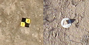
Two examples of GCPs. The one on the left is a retroreflective target
and the one on the right is a paper plate with a rock on it.

Step 2

Take aerial photographs of the project area.  The photographs need to be taken high enough from the ground to view the GCPs, but low enough that resolution is not lost.  The higher you fly, the lower the resolution of the ground.  The lower you fly the more photographs and GCPs are needed.  It is a balancing act.  It is normally best to take photographs from various heights to insure proper coverage.  I normally take three to four thousand photographs - and review the images periodically during the process.
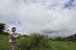
Taking aerial photographs of the site with a KAP rig.
A few of the aerial photographs taken from the kite.

Step 3

Record the location of each GCP.  Ideally, this is done with a Total Data Station (TDS).  A TDS will record highly accurate X, Y, and Z coordinates for each GCP. An alternative method is to use a GPS with a barometric altimeter.  I have tested an inexpensive Garmin Map 60Cx with this process and it works reasonably well, but the accuracy suffers.  Whichever method is used, save the coordinates to text file with the name "RealWorldGCPs.txt".
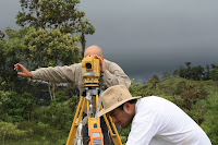
Recording the locations of the GCPs with the TDS.
Note: This method has only been tested with metric coordinates (ie. UTM) but it should work also work with data in decimal degrees.

Step 4

The next task is to cull the images.  Removing blurry and off-subject photographs is especially important when the photos come from blimp aerial photography (BAP) or kite aerial photography (KAP). Try to have 400 to 600 highly overlapping ‘in focus’ photographs of your subject matter.  Do not edit the photographs. Editing the photographs can cause problems in the next step.

Step 5

Process the photographs with Photosynth or Bundler.  This involves uploading your images to Photosynth or through the stand alone Bundler SfM application. 

Step 6

Review the point cloud data.  The creation of the point clouds often hits a snag and produces bad data.  To view the point cloud in Photosynth, press the "P" on your keyboard a couple of times while viewing the synth.  This will step through showing photographs and point clouds.  If your project has a low synth value or has a large amount of points in places they should not be, reprocessing of the data is needed.  Try adding or removing photographs to improve the model.  This involves re-uploading and reprocessing your images. Ideally, the project will be “100% Synthy” on Photosynth’s “Synthy” scale but 100% “synthiness” is not mandatory to get good results.
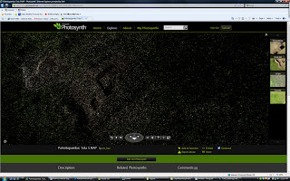
The point cloud as viewed in Photosynth.

Step 7

Extract the point cloud. If using Photosynth, the free Photosynth Exporter application can extract the data.  In Photosynth Exporter, select "From URL" and then paste the synth URL into the open field.  To follow along with my data use the URL " http://www.photosynth.net/view.aspx?cid=14d8887c-7475-42d5-b810-c6642eace2c5 ". Make sure PLY (ASCII) (not binary) is selected.  A new dialog box will open, from "Select point clouds to export" choose the default option of "0*" and then click "Ok". Name it "Tola_5_0.ply". If denser point clouds are needed, use Photosynth’s Tool Kit.  Either process will produce a PLY model of the point cloud.
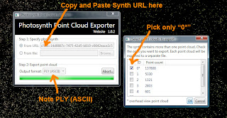
Download the point cloud with Photosynth Exporter.

Step 8

Open the file "Tola_5_0.ply" and edit the point cloud using the free and open source Meshlab software.  It is likely that some stray points or noise exist in the point cloud and need to be removed.  Use Meshlab's "Select Vertexes" and "Delete the current set of selected vertices" tools to accomplish this. 
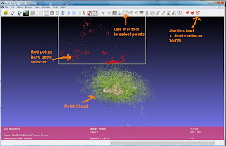
Editing the point cloud in Meshlab.

Step 9

Save the edited point cloud with the name "Tola_5_0_edited.ply" again - make sure it is an ASCII (not binary) formatted PLY.
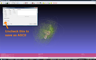
Saving the edited point cloud as an ASCII file in Meshlab.

Step 10

Open the newly edited point cloud file "Tola_5_0_edited.ply" in a text editor like Notepad and delete the header. 
The part you want to delete will look similar to this:
plyformat ascii 1.0comment VCGLIB generatedelement vertex 134399property float xproperty float yproperty float zproperty uchar redproperty uchar greenproperty uchar blueproperty uchar alphaelement face 0property list uchar int vertex_indicesend_header
This will leave only the set of X, Y, and Z attributes.  Save the file with the name "pointcloud_edited.XYZ". This file will be used later in the tutorial.
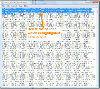
Removing the header from Tola_5_0_edited.ply.
The edited file ready to save as pointcloud_edited.XYZ.

Step 11

Next open "Tola_5_0.ply"  from Step 8 (Not "Tola_5_0_edited.ply") in Notepad and delete the header.
The part you want to delete will look similar to this:
ply
format ascii 1.0
element vertex 137808
property float x
property float y
property float z
property uchar red
property uchar green
property uchar blue
end_header
This will leave only the set of X, Y, and Z attributes.  Save the file with the name "pointcloud_UNedited.XYZ". This file will be used later in the tutorial.
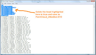
Removing the header from Tola_5_0.ply.
The file ready to be saved as pointcloud_UNedited.XYZ.

Step 12

The next several steps were developed by Nathan Craig and are also outlined on his blog.  They are recreated here with his permission. Note that my method does not maintain the point cloud vertex color as it is not needed/used in DEM creation.
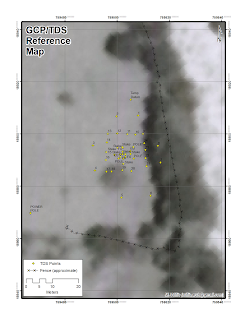
ScanView is a free program to view and mark points within a point cloud.  You can use the import command to open the "pointcloud_UNedited.XYZ"  file saved in Step 11.  Use Scanview to locate the GCPs in the point cloud. Often it will be impossible to relocate all the GCPs in more sparse point clouds.  Focus on finding four or more widely distributed GCPs, if possible.  As GCPs are located, use the measure tool to record the location of each by pressing SHIFT and Left Clicking.  It is useful to write down which Scanview point cloud GCP number corresponds to the physical GCP numbers created in Step 3.  In other words, the GCP that was placed in the field may be GCP 12 but it corresponds to point cloud location 3 as recorded in Scanview.  I find it useful to have a printout of the GCPs real locations on a Google Earth background for reference and to use field notes.
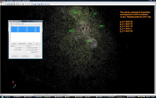
Marking GCPs in ScanView.
Map used for reference.

Step 13

Once finished with identifying the point cloud GCPs, click the copy button in the measure tool.  This saves the data to the computer's virtual clipboard.  Open Notepad and paste this data into an empty file.
This will produce a tab delimited array according to the following format:
ID X Y Z
ID = the ScanView's point cloud GCP number.
XYZ = the point cloud location for each GCP.  These will often be values less than “10" and greater than “-10”.
Save this file as PointCloudGCPs.txt
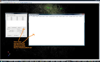
Copying the points from ScanView to Notepad.

Step 14

Open Excel or similar spreadsheet program. Excel 2010 is capable of handling more than a million rows of data.  Older versions of Excel and all versions of Open Office can only handle about 65,000 rows of data.  This is important to note because most high resolution point clouds will have hundreds of thousands of points.
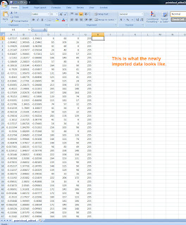
In Excel, go to Open and then choose the file type as "Text Files". Navigate to the location of the file PointCloud_edited.XYZ from Step 10.  In the filename box, type "*.XYZ" to make the file visible to Excel and then double click on the PointCloud_edited.XYZ file to open it.  A Text Import Wizard will pop up. Make sure the radio button for Delimited is selected and then click Next.  Depending on how the data was saved, you'll either need to select the "Space" or "Tab" boxes to properly delimit the file.  You will know you have it right when six vertical lines appear in the data preview box that divides the data into seven columns.  Click Finish and six columns of numbers should appear in the spread sheet.  The columns are in the format of X Y Z R G B 255.  The “XYZ” being the point cloud location of each point and “RGB” is the color value for each point.
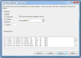
Importing PointCloud_edited.XYZ into Excel.
The file PointCloud_edited.XYZ after import into Excel.

Step 15

The columns must be rearranged and modified for use in later steps.  In the Excel spread sheet, add a new column to the left of XYZ and delete the RGB and 255 columns.  This will leave the data in following format:
B X Y Z B B B B
B = BLANK/Empty column
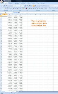
PointCloud_edited.XYZ with unneeded columns removed and reorganized

Please note this process ignores the RGB values because they are not significant for the final DEM.  If you plan on using the data in 3D Studio Max or similar program, it may be useful to maintain these values.  See Nathan Craig's blog for more information on this.

Step 16

Open the file PointCloudGCPs.txt in Notepad. Select all the points and paste them into first rows of the PointCloud_edited.XYZ file opened in Excel.  This will replace several rows of data at the top of the file.  You may need to manually reformat this file in Notepad to get it to paste correctly.  Now select the first B column and use Excel's FILL command to add a series of numbers for each of the rows in the file.  This should start with 0 and end with whatever number aligns with your last row of data.  For each of the other columns, fill the rows with a value of 0. It should look something like this:

Step 17

Now select all the data in the Excel file and press CTRL-C to copy the data to the clipboard.  Next, open a new Notepad document and paste (CTRL-V) the data into it.  Save this file as "PointCloud_proc.txt" and close it.  Also save the Excel data as a backup before closing the program, in case a problem is encountered.
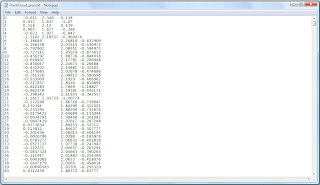
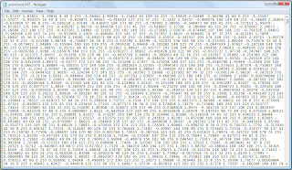
PointCloud_proc.txt

Step 18

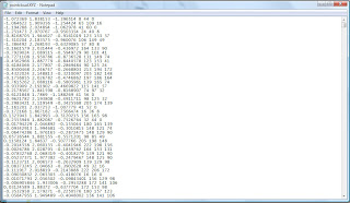
Now open the "RealWorldGCPs.txt" file that was created in Step 3.  This file contains the real world locations of the GCPs but must be reformatted so that data in each row corresponds to each row of data in PointCloudGCPs.txt.  This may mean that rows need to be switched, renumbered, and removed.  Use notes and other reference materials noted in Step 12 to help with this task. Save the new file as "RealWorldGCPs_Reformatted.txt".
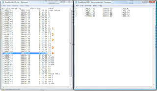
Matching the GCPs in RealWorldGCPs.txt to corresponds
to each available point in PointCloudGCPs.txt.

Step 19

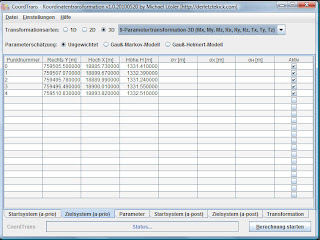
The data is now properly formatted for use in the open source Java Graticule 3D (JAG3D) program. JAG3D transforms the arbitrary synth coordinate system into a real world coordinate system.   The commands for transforming the data are only available in German.  Open the program by double clicking the JAG3D.exe icon, click Module, and then choose Coordinate transformation (German only).  This will open a new window.  Make sure the 3D radio button is selected.  Next pick the 9-Parametertranformation-3D (Mx, My, Mz, Rx, Ry, Rz, Tx, Ty, Tz) from the drop down menu.  Now click Datei in the upper left of the menu and then Import Startsystem.  Next, pick the file "PointCloud_proc.txt" that was saved in Step 17.  This may take a while to open.  Once it has opened, click Datei again and then Import Zeilsystem. Now pick the file "RealWorldGCPs_Reformatted.txt" that was created in Step 18. To perform the transformation, click the "Berechnung starten" button in the lower right of the CoordTrans window.  This may take several minutes to complete.
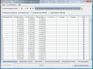
PointCloud_proc.txt loaded into JAG3D.
RealWorldGCPs_Reformatted.txt loaded into JAG3D.

Step 20

To export the transformed coordinate file, click Datei in the upper left of the window and then Export Transformation.  Save this file with the name PointCloudinRealWorldCoordinates_trans.txt.
The data is now properly formatted, transformed, and is ready to be converted into a DEM.  The process for doing this in ArcGIS via the Spatial Analyst tool is explained here, but there are different software options available that are capable of this such as Golden Software's Surfer, ERDAS Image, or the open source GRASS software.

Step 21

The file PointCloudinRealWorldCoordinates_trans.txt must be imported into Excel.  The easiest way to do this is to open a new workbook in Excel.  Next, open PointCloudinRealWorldCoordinates_trans.txt in Notepad.  Select all the data (CTRL-A) and copy it to the clipboard (CTRL-C).  Now click the first column and row in Excel and paste the data (CTRL-V).  To create a header that ArcGIS can read, name the first column "Number", the second column "Easting", the third "Northing", the fourth "Elevation" and the final three columns A, B, and C.  Save this file in Excel's native format PointCloudinRealWorldCoordinates_trans.XLSX.
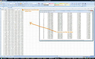
Bringing the JAG3D transformed output back into Excel.

Step 22

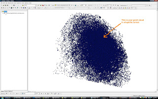
Open ArcGIS. We will need to create a shapefile from the transformed point cloud data using the Add XY Data tool.  Go to the main tool bar select Tools > Add XY Data.  Now navigate to the file saved in Step 21 (PointCloudinRealWorldCoordinates_trans.XLSX) from the "Choose a table from the map or browse for another table:" drop down.  Pick "Sheet 1" and click Ok. For the X Field choose the Easting (X) column. From the Y Field pick the Northing (Y) column.  Next define the coordinate system by choosing Edit from the lower left. The tutorial data is in the UTM Zone 17 North PSAD 56 projection. This will create an entry under Layers called "Sheet1$ Events" or something similar.  Right click on this file and choose Data > Export Data.  A warning "Table does not have Object_ID field" will appear. Click "Ok".  It will ask for an Output shapefile or feature class.  Call it "PointCloudinRealWorldCoordinates_trans.shp" and click OK. ArcGIS will ask if you would like to add the new shapefile as a layer.  Click yes. A new shapefile called PointCloudinRealWorldCoordinates_trans should appear in the layers display.  To keep this from becoming confusing, remove "Sheet1$ Events" by right clicking it and choosing "Remove".
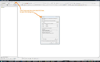
Importing the transformed point cloud from Excel into ArcGIS.
Converting the Excel data into a shapefile.

Step 23

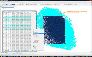
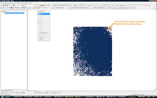
ArcGIS is not good at dealing with irregularly shaped point clouds during the DEM creation process. In order to make the dataset more ArcGIS friendly, the dataset must be rectangular.  To accomplish this, use the "Editor" drop down and then select "Start editing".  Next make sure the "Edit Tool" is active (It is the little black triangle next Editor drop down).  Now select a rectangular or square area that is entirely contained within the "PointCloudinRealWorldCoordinates_Trans" shapefile. Right click on "PointCloudinRealWorldCoordinates_trans" in the Layers window and then select "Open attribute table".  This will open a spread sheet of attributes for the shapefile.  Pick "Options" from the lower right of the spread sheet and then click "Switch Selection".  A warning may appear that says "This table (potentially) contains a large number of records... Do you want to continue?".  Click Yes and the data outside of your original selection will become active. Now click "Delete" from your keyboard to remove these outside points.  A rectangle of points should be left. Close the "Attributes of PointCloudinRealWorldCoordiantes_trans" by clicking the X in the upper right corner of that window. Save the edits by clicking the Editor drop down and then choosing "Stop Editing".  A window will open asking if you want to save the edits.  Pick Yes.
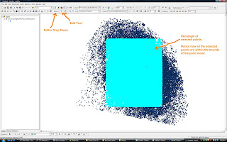
Selecting a rectangular area to become a DEM from the irregular shapefile.
Inverting the selection and deleting the points outside of the rectangular area.
The remaining points to create the DEM with.

Step 24

Now, make sure that the Spatial Analyst tool is visible in ArcGIS.  If it is not, from the main tool bar select Tools > Customize and then put a checkmark next to "Spatial Analyst" and then click Close.  Now in the Spatial Analyst tool bar choose "Interpolate to Raster and then Kriging". This will open the Kriging dialog box.  For Input points: choose the shapefile "PointCloudinRealWorldCoordinates_trans.shp".  For Z value field: pick the Elevation or Z column.  Adjust the output cell size to value that is appropriate for your data.  It is often best to leave this at default at first. Everything else should be ok to leave as is. Click Ok.  A new file "Krige of PointCloudinRealWorldCoordinates_trans" should appear after a few minutes.  This is your DEM! 
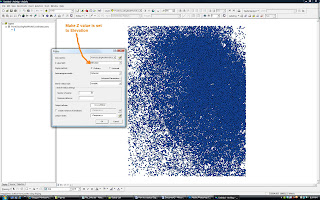
Using Spatial Analyst to create temporary DEM.

Step 25

To save the DEM, right click "Krige of PointCloudinRealWorldCoordinates_trans" and pick Data > Export Data.  A dialog box will open.  Name the file "DEM_PointCloudingRealWorldCoordinates_trans.img" and use the IMG format and click Save.

There are many things that can affect the quality of a DEM. The point cloud data used in this tutorial was collected on a windy day from a kite aerial photography rig.  Much of the ground vegetation was moderately tall grasses and small shrubs.  Since it was windy, the vegetation was constantly swaying and changing position slightly.  This produces “noise” during the synth matching process.  Furthermore, near the excavations there were several poles, an excavation screening tripod, and a tarp protruding above the ground surface.  These points have created "spikes" in the DEM.  The spikes could have been minimized by more aggressive editing during Step 8.
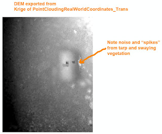
The DEM

Step 26

Have a cold beer.  You deserve it! Maybe you'd like to buy me one?  Click the donate button at the top right of this page!

Optional Steps

Step 27 - Create Contours

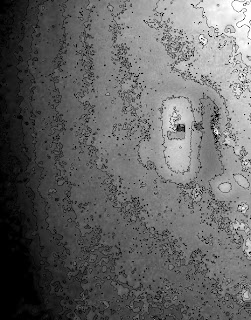
To create topographic contours of the DEM, go to Spatial Analyst drop down and pick Surface Analysis and then Contour. A dialog box will open.  From there choose "Input surface" as DEM_Point_CloudinRealWorldCoordiantes_trans.img" and then pick a Contour interval of 0.5 meters. Under Output Features save the file as "Tola_5_50cm_Contours.shp" and click Ok.
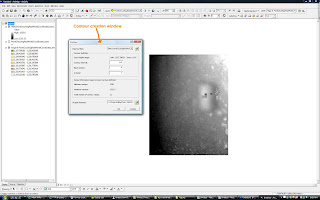
Generating topographic contours in Spatial Analyst.

50 centimeter contours on DEM.
 Step 28 - Georeference Aerial Photograph
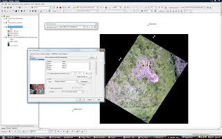
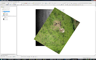
The Georeferencing tool is made available by clicking Tools from the main menu, then Customize, putting a checkmark next to "Georeferencing", and clicking Close. Add an aerial photograph that covers a lot of the project area by clicking "Add Data" and picking "IMG_4197.JPG" (available from www.palentier.com/DEM_Tutorial/ ). A warning about Unknown Spatial Reference will appear.  Click Ok to proceed and add the image to the Layers window. Add the shapefile "Tola_5_TDS_UTM_Points" from www.palentier.com/DEM_Tutorial to the Layer's window as well. In the Georeferencing tool, make sure the Layer dropdown has "IMG_4197.JPG" active and then click the "Add Control Points" tool (The icon looks like a green x with a line drawn to a red x). Match the GCP plates on the JPG to the points in the Tola_5_TDS_UTM_Points shapefile.  The aerial image will start to line up with the portions of the DEM.  As the image was not taken perfectly nadir and contains lens distortions, it is impossible to completely align all the GCP plates with the shapefile points.  Line it up as best as possible, knowing that distortion is present.  Removal of the distortion is a subject for another tutorial...  Once you are satisfied with alignment, click Georeferencing, then click rectify, name it "IMG_4197_Rectified.img" and save the new image.  The original IMG_4197.jpg can now be removed from the Layers windows and the new IMG_4197_Rectified.img can be added.  Double click the "IMG_4197_Rectified.img" file from the Layers window.  The Layers Properties dialog box will open.  Select the Symbology tab and place a check mark next to "Display Background Value (R, G, B), under Stretch Type choose "Minimum-Maximum", and then click Ok. There should now be a georeferenced aerial image above the DEM.
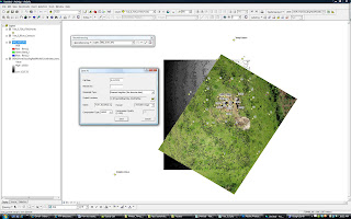
Georeferencing the aerial photograph.
Removing black background and fixing colors.
Properly aligned aerial with DEM and contours.
An example of the results of this process, when exported to Google Earth, is available here:  http://www.palentier.com/DEM_Tutorial/Tola_5_DEM_and_Aerial.kmz

Step 29 - Visualing the Data in 3D

Use ArcScene to visualize your data as seen in this Youtube video:

Notes:

  • If your dataset is very large, you might want to break it into several smaller sets.  I have found that point clouds of around 100,000 points process happily in JAG3D.  Larger point clouds (1 million+ points) can take forever to transform or may crash. Breaking the point clouds into smaller batches is also a good way to get around the 65,000 column limit in older version of Excel or in Open Office.  To do this break the points from Step 10 into several smaller groups of points AFTER completing Step 13 and then follow the rest of the tutorial for each group of points through Step 20.  The same PointCloudGCPs.txt file can be used for each group of points during the JAG3D transformation process. After all the groups of points have been transformed, copy and paste the contents of each group into one large text file (just add one group at the end of the next) and then proceed with the rest of the tutorial.
  • Consider the output number of digits in your transformed data.  Some software, like 3DS Max and Meshlab, will not properly handle numbers with lots of digits.  You may need to remove several leading digits (as explained here) to make your data render properly.
  • If any of your GCPs were not identifiable in the point cloud but their location is within the boundary of the DEM, you can double check the DEM accuracy by comparing the GCP's Z value with the DEM's Z value.

Useful Links:

Nathan Craig's Blog posts:

Josh Harle's Tutorials: